Diagram Of Compression Cooling System Cpr Chest Compressions
Schematic diagram of cooling system, (a) conventional vapor compression Schematic drawing of compression and cooling. reproduced with Understanding thermal systems: basic cooling systems
Compressed Air Systems (Energy Engineering)
Vapor-compression cycle Vapor compression cycle – isaac's science blog Working of engine cooling system
How vapor compression refrigeration system works
Refrigeration compression vapor function conditioning absorption explainedCompressed air systems (energy engineering) Cooling compressed compressorsHow an engine cooling system works.
Abandonat om bogat moştenitor ts diagram for a one stage vaporCooling system using compressed air ★engine cooling system and what it consists of★Compressed air system schematic systems engineering energy fig.

Compression parallel range dynamic compressor upward diagrams gain level reduction make mastering effect these figure article levels types set
Basic cooling thermal systems cycle compression vapor insulation refrigeration gas natural understanding marine equipment large chemical petrochemical smallAvoid cooling system damage Refrigeration compression vapour vapor refrigerator vcc exchanger component araner mechanicalCooling loop dual system furnace water vacuum schematic tower closed heat exchanger coolant pump gif side.
Compression refrigeration vapor refrigerator vapour evaporator expansion condenser timetoastCompressed air diagram schematic unit food compressor system water producing figure steam components dairy maintenance engineering Vapor compression refrigeration systemDairy and food engineering: lesson 30. compressed air, water and steam.

Cooling engine system car working coolant systems works vehicle does heat water cooled components block used fan through types main
Cpr chest compressions perform medicalnewstoday breaths different rescue procedure nursing breath arrest receives eriksen cardiac victim techniques riseHow does a compression refrigeration system work? Refrigeration compression vapor refrigerant heatParallel compression.
Forced circulation water cooling systemCooling diagram system toyota automotive coolant engine car process flow radiator air parts automobile 123rf saved vector Schematic compression cooling vapor conventionalSchematic drawing of compression and cooling. reproduced with.

Figure 5-1 from observer-based engine cooling control system ( obcool
Cooling system engine car diagram does work vehicle works components maintain tweet autozoneThis is the hvac tech that will replace vapor compression Cpr steps: a visual guideCycle compression vapor refrigeration thermodynamic conditioning thermodynamics cycles nuclear.
Dual loop furnace cooling systemSchematic diagram of a typical vapor compression refrigeration cycle 17 Basic vapor-compression cooling system schematic diagram.How does a car's cooling system work? (& how to maintain it).

Cooling system engine gasoline automobile britannica radiator coolant air through fan fresh
Cooling system: compressed air cooling system[diagram] vapour compression refrigeration cycle t s diagram Engine cooling system diagramPin on toyota corona.
A simple diagram of vapour compression refrigeration cycle andSimple vapour compression refrigeration system Sale > cooling cycle > in stockCooling coolant radiator circulates component principles overflow howacarworks wiring helper schematic heater automobil.


Pin on Toyota corona

Engine Cooling System Diagram

Abandonat Om bogat Moştenitor ts diagram for a one stage vapor

How an engine cooling system works | How a Car Works

Sale > cooling cycle > in stock

Schematic diagram of cooling system, (a) conventional vapor compression
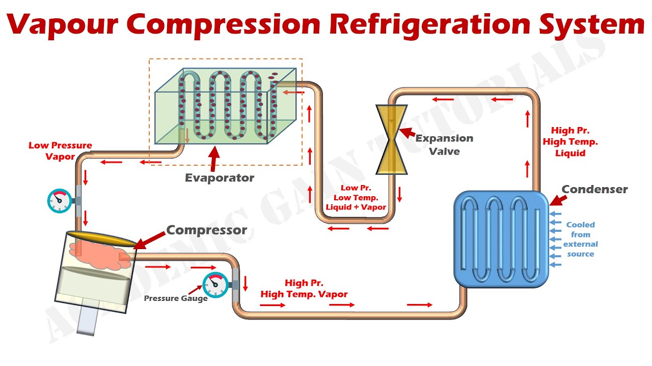
How Vapor Compression Refrigeration System Works - Parts & Function